
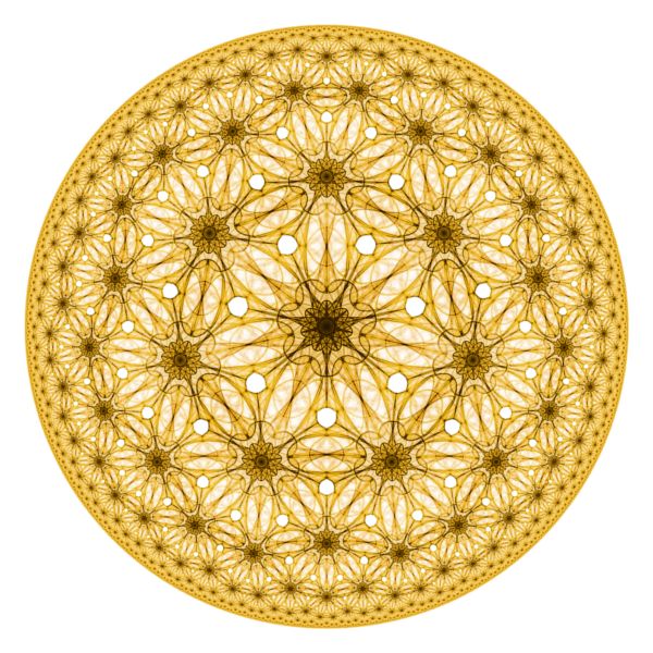
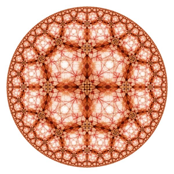
Hyperbolic Attractor Examples
Life |
Taking Root |
Briar Patch |
Wicker World |
Mediterranean Tile |
Aztec Sun |
Solar Energy |
Blue Rose |
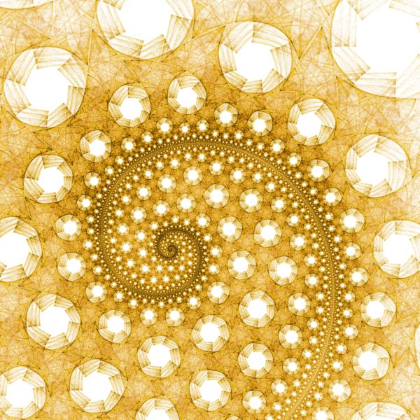
Honey |
Elven Shield I |

Elven Shield II |

Ring of Stars |

Ring of Holes |
Dreamcatcher I |
Dreamcatcher II |
Precarious Path |
Red Star |
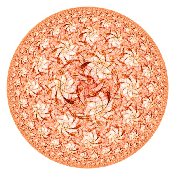
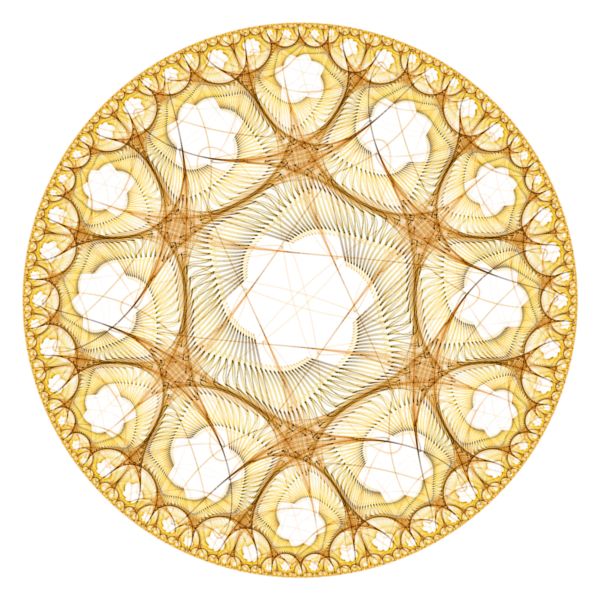
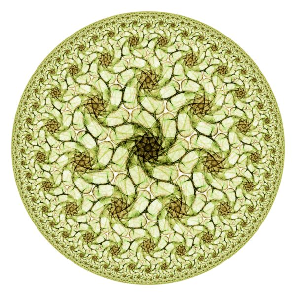
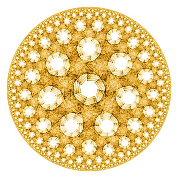
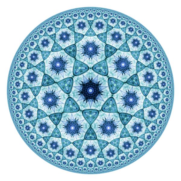
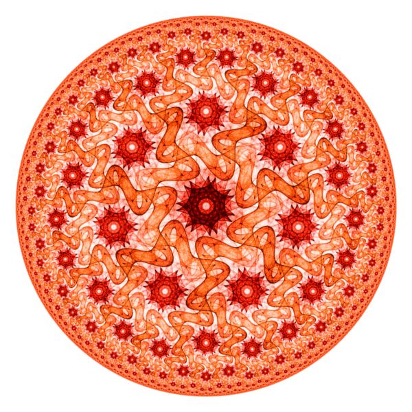
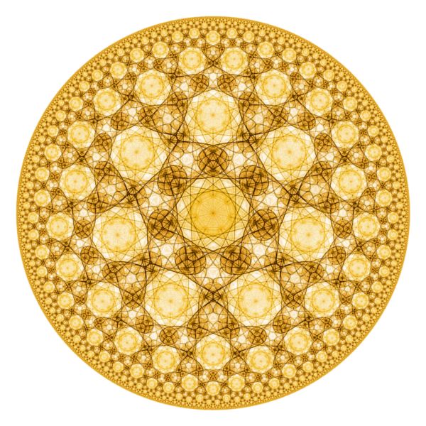
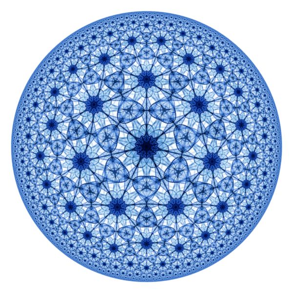
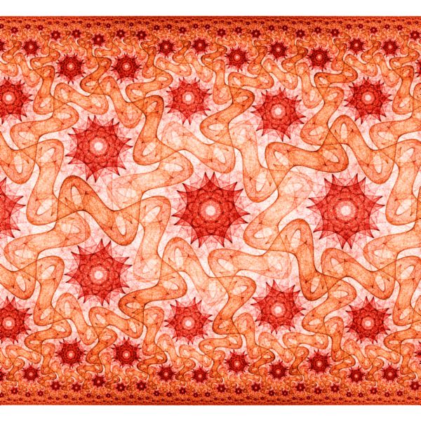
The Hyperbolic Attractor examples display a fractal generated from one of the Symmetric Icon or Symmetric Attractor examples in the context of the Symmetry Transformation Hyperbolic Tiling - Orbital.
Note the following:
| Example | [p,q] Tiling | Orbital Equation |
| Hyperbolic Attractor 01 | [3,7] | Symmetric Icon - Variations |
| Hyperbolic Attractor 02 | [6,4] | Symmetric Icon - Variations |
| Hyperbolic Attractor 03 | [7,3] | Symmetric Icon - Variations |
| Hyperbolic Attractor 04 | [7,3] | Symmetric Icon - Variations |
| Hyperbolic Attractor 07 | [7,3] | Symmetric Icon - Non-Polynomial Term |
| Hyperbolic Attractor 08 | [7,3] | Symmetric Icon - Non-Polynomial Term |
| Hyperbolic Attractor 10 | [7,3] | Symmetric Icon - Non-Polynomial Term |
| Hyperbolic Attractor 11 | [7,3] | Symmetric Icon - Non-Polynomial Term |
| Hyperbolic Attractor 12 | [7,3] | Symmetric Icon - Non-Polynomial Term |
| Hyperbolic Attractor 13 | [4,5] | Symmetric Attractors |
| Hyperbolic Attractor 14 | [4,5] | Symmetric Attractors |
| Hyperbolic Attractor 15 | [7,3] | Symmetric Icon - Non-Polynomial Term |
| Hyperbolic Attractor 16 | [7,3] | Symmetric Icon - Variations |
| Hyperbolic Attractor 17 | [4,5] | Symmetric Attractors |
| Hyperbolic Attractor 18 | [4,5] | Symmetric Attractors |
| Hyperbolic Attractor 19 | [7,3] | Symmetric Icon - Variations |
| Hyperbolic Attractor 20 | [7,3] | Symmetric Icon - Non-Polynomial Term |
See Symmetric Icon and Symmetric Attractor for examples of the fractals produced by these Orbital Equations but without the hyperbolic tiling.
See the section Hyperbolic Tiling - Orbital below for an explanation of the [p,q] notation used in the table above.
In the remaining sections, when I refer to the equation, I will use Symmetric Icon - Variations, but you should use the equation for the example you are working with.
Performance
The examples are based on the Hyperbolic Tiling - Orbital symmetry transformation. There are a few properties associated with the symmetry transformation that are related to quality and also affect performance. When you are exploring, you can improve performance by adjusting these properties on the symmetry transformation's properties page.
Select the symmetry transformation's properties page:
General
Orbital / IFS / Strange
Attractor
Symmetry Transformation: Hyperbolic Tiling - Orbital
Properties
The border of the Poincare disk represents infinity with respect to the hyperbolic plane. As the tiling approaches the disk border, the polygons get smaller and smaller. The Epsilon value determines how close to get to the Poincare disk border when generating polygons. Smaller values of Epsilon close the gap between the disk image and the true border, resulting in a smoother edge on the disk. However, this also results in many more polygons near the border which can greatly increase processing time. I recommend using an Epsilon of 0.01 for experimentation and then reducing the Epsilon to 0.001 for images you want to save.
Hyperbolic Tiling - Orbital
The Hyperbolic Tiling - Orbital symmetry transformation replicates a base fractal over the hyperbolic plane represented by the Poincare disk in such a way as to form a hyperbolic tiling pattern. The Poincare disk is a model for hyperbolic geometry that maps the hyperbolic plane onto the unit disk. The Hyperbolic Tiling - Orbital symmetry transformation has options to control the tiling. The most important of these are the Hyperbolic Tiling Options named p and q. A [p,q] regular tiling of the hyperbolic plane maps a hyperbolic polygon with p sides over the hyperbolic plane such that q polygons meet at each polygon vertex. For example, a [4,5] regular tiling maps 4 sided polygons onto the hyperbolic plane such that 5 polygons meet at each polygon vertex. A regular tiling of the hyperbolic plane exists if and only if (p-2)*(q-2) > 4. So, for example, a [4,5] tiling is possible but a [4,4] tiling is not.
The Hyperbolic Tiling - Orbital symmetry transformation requires the base fractal to have N-way rotational symmetry, where N = p/Math.GCD(p,q). The Math.GCD function returns the greatest common divisor of the given arguments. If the fractal does not have N-way rotational symmetry, it is injected into the fractal automatically by the symmetry transformation. The following table gives a few examples:
| p | q | GCD(p,q) | N = p/GCD(p,q) |
| 3 | 7 | 1 | 3 |
| 3 | 8 | 1 | 3 |
| 4 | 5 | 1 | 4 |
| 4 | 6 | 2 | 2 |
| 4 | 7 | 1 | 4 |
| 4 | 8 | 4 | 1 |
| 5 | 4 | 1 | 5 |
| 5 | 5 | 5 | 1 |
| 5 | 6 | 1 | 5 |
| 5 | 7 | 1 | 5 |
| 5 | 8 | 1 | 5 |
| 6 | 4 | 2 | 3 |
| 6 | 5 | 1 | 6 |
| 6 | 6 | 6 | 1 |
| 6 | 7 | 1 | 6 |
| 6 | 8 | 2 | 3 |
| 7 | 3 | 1 | 7 |
| 7 | 4 | 1 | 7 |
| 7 | 5 | 1 | 7 |
| 7 | 6 | 1 | 7 |
| 7 | 7 | 7 | 1 |
| 7 | 8 | 1 | 7 |
Normally, the entire fractal is replicated over the hyperbolic plane to generate the tiling. However, if you check Restrict Domain, the fractal is clipped to the central polygon of the tiling and only the part of the fractal inside the central polygon is used to tile the plane. If you check Restrict Domain, the places where the fractal intersects an edge of the central polygon should be symmetric about the edge midpoint since the polygon is rotated 180 degrees about each edge's midpoint to generate the tiling. This requirement can be ignored if you select the Reflect option which reflects about each edge rather than rotating about each edge midpoint.
The Order and Dihedral options in the section labeled Hyperbolic Tiling Attractor Symmetry Options can be used to inject additional rotational or dihedral symmetry (i.e., reflective symmetry about the X axis) into the attractor, if desired. Also, if the attractor exhibits rotational symmetry with an order higher than N or has dihedral symmetry, you can set these options to match the attractor symmetry to improve the efficiency of the fractal generation.
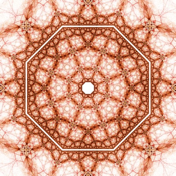
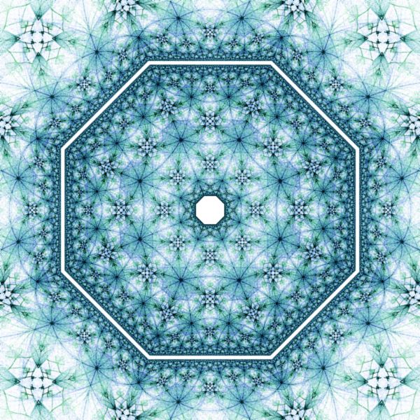
The Shape option can be set to Disk, Strip, or Ring. The Disk setting is the default and results in a [p,q] regular tiling of the hyperbolic plane mapped to the unit disk. The Strip and Ring settings cause additional transformations to be applied that change the resulting shape. Each of these settings enable the Order option that controls the complexity of the shape. For the mathematical basis for these settings (and more), see the pages Conformal Models of the Hyperbolic Geometry and Artistic Models of the Hyperbolic Geometry by Vladimir Bulatov.
The Show Inversion option, if checked, applies a circle inversion transformation to the disk to display the tiling outside the disk as well. The Weight option controls the weight assigned to points generated outside the disk and the Separation option controls the gap between the inside and outside of the disk.
The Scale Factor and Rotation options are applied to the base fractal before the fractal is replicated to form the hyperbolic tiling. The Scale Factor option is used to scale the fractal up/down. For the best results, the fractal should be about the size of the central polygon of the tiling. Check Normalize to scale the fractal relative to the central tile (i.e., the unit disk is scaled to fit just within the central polygon), otherwise the scale factor is applied directly to the fractal. The Rotation option rotates the fractal. By changing the Scale Factor and Rotation options, you can produce many different tiling designs from a single base fractal.
The border of the Poincare disk represents infinity with respect to the hyperbolic plane. As the tiling approaches the disk border, the polygons get smaller and smaller. The Epsilon value determines how close to get to the Poincare disk border when generating polygons. Smaller values of Epsilon close the gap between the disk image and the true border, resulting in a smoother edge on the disk. However, this also results in many more polygons near the border which can greatly increase processing time. I recommend using an Epsilon of 0.01 for experimentation and then reducing the Epsilon to 0.001 for images you want to save.
The Power, Factor, and Decay options control the weights assigned to the polygons that make up the tiling. Power is used to concentrate more/less points near the disk border. Factor is used to concentrate more/less points in central polygon. Decay is used to reduce point density variation within the polygons.
The base fractal should fit entirely inside the unit disk. Parts of the fractal outside the unit disk are discarded.
Play with the Symmetry Transformation Properties
You can change the properties that define the hyperbolic tiling symmetry transformation.
Select the symmetry transformation's properties page:
General
Orbital / IFS / Strange
Attractor
Symmetry Transformation: Hyperbolic Tiling - Orbital
Properties
Epsilon controls how close to get to the Poincare disk border when generating polygons and was discussed above in the Performance section.
Change the properties on this page to control the hyperbolic tiling. See the section Hyperbolic Tiling - Orbital above that describes these options. I recommend you play with the options Shape, Order, Show Inversion, Separation, Scale Factor, and Rotate.
Important: The Hyperbolic Tiling - Orbital symmetry transformation requires the base fractal to have N-way rotational symmetry as described above. Consequently, the values for p and q should be based on the rotational symmetry present in the base attractor. For example, if the base fractal has 4-way rotational symmetry, the values you choose for p and q must be such that 4 is a multiple of N (i.e., N would need to be 1, 2, or 4). Based on the table above, choices for [p,q] would include [4,5], [4,6], [4,7], [4,8], [5,5], [6,6], or [7,7].
Play with the Orbital Equation's Properties
You can change the equation's properties for more variations.
Select the equation's properties page:
General
Orbital / IFS / Strange
Attractor
Orbital Equation: Symmetric Icon -
Variations
Properties
Change the Icon property (or the Item property for the Symmetric Attractors equation) to select one of the preset designs.
The remaining properties should not be changed.
Important: Changing the Icon or Item property may change the rotational symmetry present in the base attractor. The symmetry is given by the Symmetry option for the Symmetric Icon examples and by the Symmetry setting in the text of the selected Symmetry Attractor for the Symmetry Attractor examples. The symmetry of the base fractal is important because the Hyperbolic Tiling - Orbital symmetry transformation requires the base fractal to have N-way rotational symmetry as described above. Consequently, you may need to adjust p and/or q on the Hyperbolic Tiling - Orbital properties page based on the rotational symmetry present in the base attractor. For example, if the base fractal has 4-way rotational symmetry, the values you choose for p and q must be such that 4 is a multiple of N (i.e., N would need to be 1, 2, or 4). Based on the table above, choices for [p,q] would include [4,5], [4,6], [4,7], [4,8], [5,5], [6,6], or [7,7].
Change the Point to Track
Normally, an Orbital Fractal collects statistics during the orbit of a fractal formula and uses these to create the fractal image. Rather than tracking the orbit point as is normally the case, you can track a triangle metric point instead. That is, as the orbit progresses, you use the last 3 orbit points to define a triangle, compute a triangle metric point based on the triangle, and accumulate statistics into the triangle metric point rather than the original orbit point as is normally done. Starting with any of the examples, you can produce many different variations simply by varying the triangle metric calculation.
To do this, select Orbital / IFS / Strange Attractor:
General
Orbital / IFS / Strange
Attractor
Set the Point to Track property to Triangle Metric Point.
Next, select the Triangle Metric:
General
Orbital / IFS / Strange
Attractor
Triangle Metric
Change the Triangle Metric property in the p1 section. You can change the other properties on this page too. See Triangle Metric for details.
Change Transformation 2
You can apply a transformation to the orbit point after applying the symmetry transformation.
To apply a transformation to the orbit point after applying the symmetry transformation, select the Identity transformation's page:
General
Orbital / IFS / Strange
Attractor
Transformation 2
Identity
Change the Based On property to select a transformation and then open the transformation's properties page (found under the transformation in the page hierarchy), and play with the transformation's properties. See Transformation Support for details.